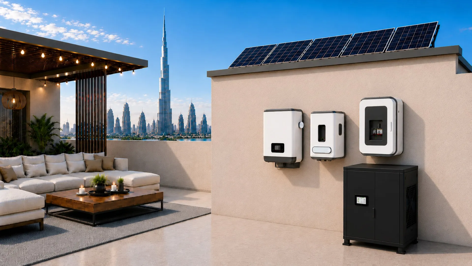
Data-centercompute,engineeredfortheoutdoors.
A sealed, IP55, 20U outdoor node carrying eight NVIDIA Blackwell GPUs through a 50 °C Gulf summer — with its own cooling, power, fire protection and control on board.
- 8×
- Blackwell GPUs
- 50°C
- Design ambient
- 7.5kW
- Peak IT load
- IP55
- Sealed envelope
baseline · scalable 4× to 16×
peaks to 55 °C
in one sealed cabinet
zero air exchange
What is different about this design
A GPU compute node that lives outdoors.
No data hall. No raised floor. No white space. The node brings its own environment with it.
The enclosure is genuinely sealed
No air exchange with ambient at all. Internal air circulates in a closed loop; heat leaves through a refrigerant circuit, not a vent. Dust, sand, salt and humidity never reach the electronics, and there are no filters to service.
Capacity is specified at the temperature of use
Every thermal component is quoted on net sensible capacity at 50 °C ambient. Nominal 35 °C ratings are treated as marketing figures and are not accepted as design inputs.
Power continuity is architected, not assumed
Solar and grid feed an automatic transfer switch; a rack-mount online UPS in double-conversion topology sits between that switch and the node, so the transfer itself is invisible to the load.
Protection is internal to the rack
A self-contained clean-agent fire suppression unit detects, isolates and extinguishes inside the sealed volume — with no room-level system, external panel or pipework.
The configuration is scalable
Four to sixteen accelerators in one architecture. Cooling capacity, UPS rating and rack height scale with GPU count, and the node is not tied to a single accelerator part number.
The node is observable
A 7-inch door-mounted HMI acts as a local DCIM head-end for every subsystem, and integrates northbound to a central platform over Modbus TCP, SNMP v3 and MQTT.
The governing design rule
Every thermal component is specified on net sensible capacity at 50 °C ambient — never on the nominal 35 °C figure.
The same discipline governs the condenser rating, the UPS derating curve and the enclosure coating class.
The problem
Compute is constrained by facilities, not by silicon.
An organisation that can obtain GPUs today may still wait years for somewhere qualified to put them. That delay is the real cost.
The facilities bottleneck
Demand for accelerated compute has outrun the rate at which conventional data-hall capacity can be built. The constraint is rarely the accelerator — it is power delivery, land, cooling plant, construction schedule and interconnection queues.
The ambient problem
Remove the building and the environment becomes a design input. In the Gulf that means sustained summer ambient in the high forties, peaks above 55 °C in direct sun, airborne dust and sand, coastal salt aerosol and wide humidity swings.
Why outdoor cabinets fail here
Telecom enclosures are dimensioned for a few hundred watts to two kilowatts, often with filtered ventilation. Against a 7.5 kW GPU node they fail on three counts at once: sensible capacity at temperature, ingress protection once penetrations are cut, and any credible fire strategy.
Design consequence
The enclosure, the cooling circuit, the power chain and the fire system cannot be selected independently and assembled. They are a single coupled system, and the sealed-envelope requirement is the constraint that drives all four.
The engineering challenge
Cooling is quoted at 35 °C. We deploy at 50 °C. Everything in the design follows from that single gap.
Every thermal component is specified on net sensible capacity at 50 °C ambient — never on the nominal 35 °C figure. The same discipline governs the condenser rating, the UPS derating curve and the enclosure coating class.
35 °C
Nominal rating
where plant is quoted
50 °C
Design ambient
where we deploy
55 °C
Peak
direct sun excursion
A unit advertised at 10 kW at 35 °C may deliver substantially less at 50 °C. Sizing on the nominal figure produces a system that works in March and fails in July.
Anatomy of the node
20U, IP55, sealed.
A 20U primary rack plus a coupled 3U power-distribution rack, with a top-mounted outdoor condenser. Every subsystem the node needs to survive alone is inside the envelope.
Coupled 3U rack · 3U
2 × 3φ 32 A horizontal RPDU-B + 1U spare
Spare U-space
1UReserved for future expansion
One rack unit held back so a field change — an extra switch, a second DPU, additional instrumentation — does not require re-cutting the enclosure.
Fire suppression
1URack-mount clean-agent detection & discharge
Detection, control and agent in a single rack-mount unit. Optical smoke and heat sensors sample the internal return-air path, where all circulating air passes.
AI compute node
4U8 × NVIDIA Blackwell GPUs · dual AMD EPYC
MSI CG480-S6053 chassis. Eight RTX PRO 6000 Blackwell Server Edition at 600 W each — roughly 4.8 kW of GPU power in 4U, front-to-rear airflow inside the sealed loop.
Online UPS
6UDouble conversion · ~3:45 autonomy at load
The node is always fed from the UPS inverter, so the ATS break — tens of milliseconds — is never seen by the load. Output stays a regulated sine wave through sags, surges and frequency drift.
Precision DX cooling
8UClosed-loop evaporator · 7.5 kW net sensible @ 50 °C
An inverter-driven compressor with EC fans modulates to load rather than cycling, holding 18–25 °C at the equipment intake as GPU utilisation swings.
Coupled 3U rack
2 × 3φ 32 A horizontal RPDU-B + 1U spare
Power distribution is carried in its own coupled enclosure so that a distribution change never breaks the seal on the compute cabinet.
Compute platform
Eight Blackwell GPUs on an MSI CG480-S6053.
AMD EPYC selected for memory topology and PCIe lane budget at this GPU count — 128 lanes per socket feed eight accelerators, the DPU and the NVMe pool without contention.
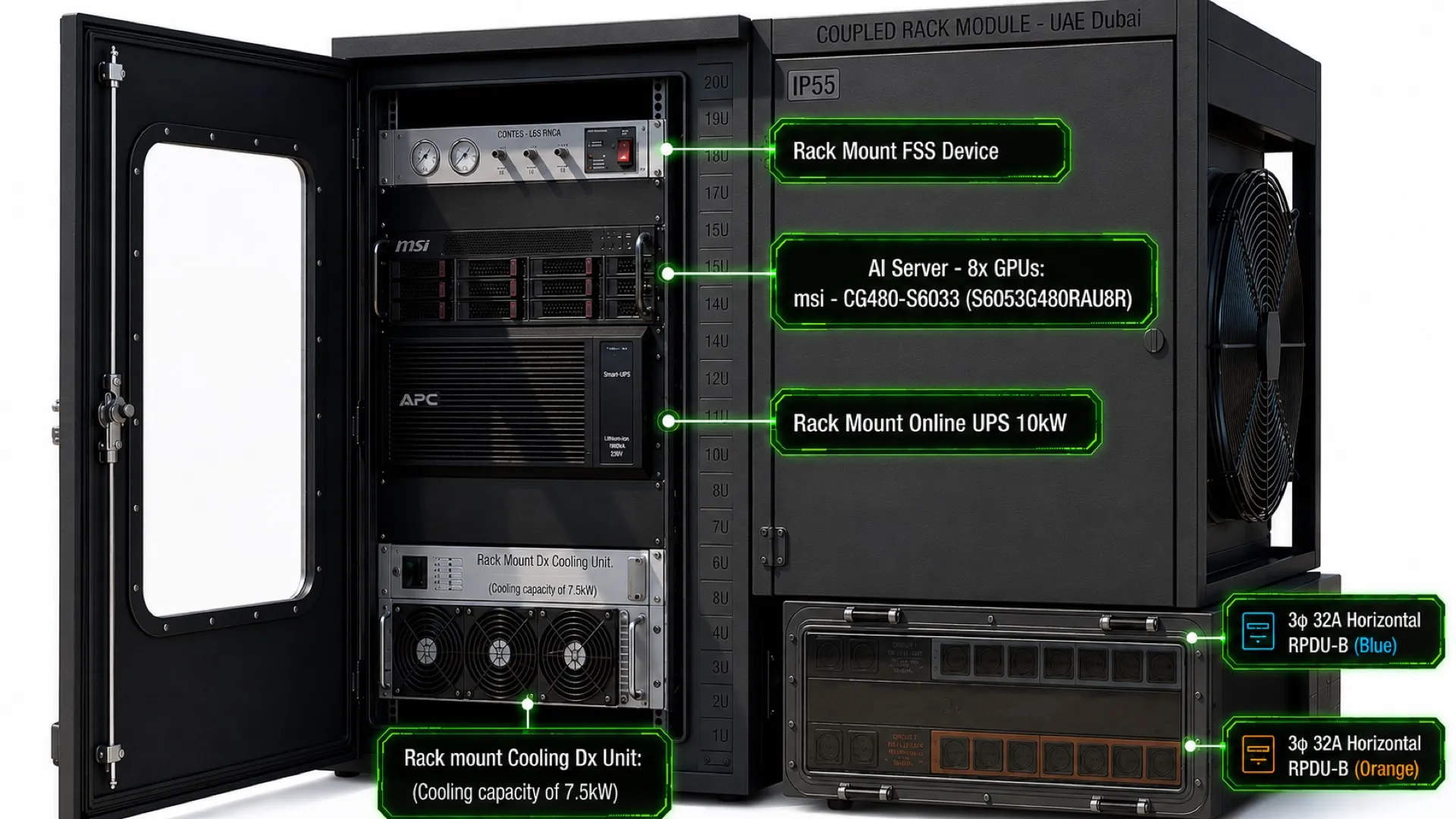
Coupled rack module · UAE Dubai · render for illustration only
~5.8 kW
Typical AC draw
~7.3 kW
Peak AC draw
~5.2 kW
GPUs capped to 400 W
Platform specification
- GPU
8 × NVIDIA RTX PRO 6000 Blackwell Server Edition
600 W per GPU · ~4.8 kW total
- CPU
2 × AMD EPYC 9575F
64 cores @ 3.3 GHz per socket
- Memory
1.5 TB DDR5-6400
24 × 64 GB · one DIMM per channel
- Storage
8 × 7.68 TB U.2 NVMe SED
+ 2 × 960 GB RAID-1 boot
- Network board
NVIDIA BlueField-3 DPU B3220
on-board
- On-board network
2 × 10GbE RJ45 LAN
- I/O budget
128 PCIe lanes per socket
feeds 8 GPUs, DPU and NVMe
- Security
On-board TPM · self-encrypting drives
- Form factor
4U rack-mount
front-to-rear airflow
Note · 600 W per GPU — roughly 4.8 kW of GPU power in a single 4U chassis, cooled by a sealed closed-loop DX system with no air exchanged with ambient.
Thermal design
A closed-loop cycle. The air inside never leaves.
Precision DX, not comfort AC — a tight setpoint held against a 50 °C exterior. Internal air circulates in a sealed loop; heat leaves through a refrigerant circuit, not through a vent.
- 01
Supply
18–25 °CConditioned air is delivered upward across the equipment intake face by EC fans in the rack-mount evaporator.
- 02
Load
~7.5 kW absorbedThe air passes through the GPU, CPU and power stages, absorbing roughly 7.5 kW of heat on a single pass.
- 03
Return
sealed plenumHeated air leaves the top of the equipment stack into a sealed internal plenum — it never touches outside air.
- 04
Reject
to +55 °C ambientThe plenum returns air to the evaporator, where heat transfers to refrigerant and is rejected outside by a high-ambient condenser rated to +55 °C.
Why the loop stays closed
The cooling unit is described by function only — component selection is finalised at build.
Zero air exchange
No outside air enters the cabinet, so dust, sand, salt and humidity never reach the electronics. Filter maintenance in the field is eliminated.
Precision DX
An inverter-driven compressor with EC fans modulates to load rather than cycling, holding a tight setpoint as GPU utilisation swings.
High-ambient condenser
The outdoor unit is rated to +55 °C and roof-mounted with vertical upward discharge, so rejected heat is not re-ingested.
Insulated, reflective shell
PIR sandwich panel over mineral insulation — low conductivity, closed-cell, no moisture uptake, under a UV-stable C4+ coating.
Sealed penetrations
Every cooling, power and data cut-out is gasketed and sealed so the IP55 rating survives integration, not just the empty cabinet.
Fail-safe on cooling loss
High-temperature alarm, staged GPU power capping, automatic graceful shutdown and emergency door release if the setpoint cannot be held.
Power architecture
Solar first, grid behind it, UPS across the gap.
Two independent sources, one automatic transfer switch, and an online UPS that hides the transfer from the node.
Automatic transfer switch
Continuously monitors both sources and holds the load on the solar-fed inverter while it stays in tolerance. On undervoltage, frequency excursion or source loss it transfers to grid, and back again once solar recovers — automatically, with no attendance.
Rack-mount online UPS, 10 kW
True double conversion: the node is always fed from the UPS inverter, so the ATS break — typically tens of milliseconds — is never seen by the load. Transfer time is effectively zero.
Ride-through and ordered shutdown
Battery autonomy covers cloud transients, inverter restarts and grid events. If both sources stay down, the UPS signals the HMI, which triggers a graceful GPU and OS shutdown before the batteries are exhausted.
Two sources, one transfer switch, five protected circuits.
| Way | Protection | Load | Supply |
|---|---|---|---|
| W1 | 32 A 3P | Online UPS 10 kW → RPDUs → AI compute node | UPS-backed |
| W2 | 20 A 3P | Precision DX cooling unit | Utility fed |
| W3 | 6 A 1P | Fire suppression unit | Utility fed |
| W4 | 6 A 1P | HMI / DCIM panel | Utility fed |
| W5 | 16 A 3P | Outdoor condenser (ODU) | Utility fed |
Single line diagram EXN-EL-001 Rev A · 400 V 3φ+N 50 Hz · TN-S earthing · 63 A main. Cooling load (~2.5–3.5 kW) sits downstream of the ATS on utility power — deliberately not on the UPS, to preserve UPS autonomy for the compute node. Aggregate design load ~11 kW. Ratings indicative, subject to a licensed electrical engineer review before issue for construction.
Monitoring & control
A 7-inch HMI is the node’s DCIM.
A standalone outdoor node has no building management system, so it provides its own. Every subsystem reports to one door-mounted touchscreen — and to your central platform.
21.4°C
Supply
38.7°C
Return
6.42kW
Node load
Solar
Source
Online
UPS mode
Armed
Fire system
Representative screen layout
Thermal
Supply and return temperature, delta-T across the load, internal humidity, setpoint and deviation, compressor and EC fan state, condenser status, and derived cooling capacity margin.
Power
Active source, input and output voltage, current, kW and kWh, power factor, UPS mode, battery state of charge and remaining runtime.
Safety
Fire system armed / alarm / discharged, door position, smoke and heat sensor state, leak detection, intrusion.
Compute
Node power draw and GPU telemetry surfaced from the platform’s own management interfaces.
Northbound integration
Modbus TCP, SNMP v3 and MQTT to a central DCIM or NOC, with local trending, event logging and remote alerting. Operators can adjust setpoints, acknowledge alarms and trigger a graceful shutdown from the panel or remotely.
Configuration range
Four to sixteen GPUs, in one architecture.
GPU count is not an isolated choice — cooling capacity, UPS rating and rack height scale with it.
20U + 3U coupled
Rack height
At sixteen accelerators the condenser and the incoming three-phase feed become the binding constraints rather than the compute. 8× is the proof-of-concept baseline; the 4× and 16× figures are indicative, pending design freeze.
Accelerator options
Not tied to one GPU.
The enclosure, cooling circuit and power chain are specified against watts and form factor — not a part number.
| Accelerator class | Board power | Effect on the node | Status |
|---|---|---|---|
| RTX PRO 6000 Blackwell SE | ~600 W | Baseline — eight fit within the 7.5 kW sealed air-cooled envelope. | Baseline |
| H200 — PCIe / NVL class | ~600 W | Comparable envelope to baseline; count and plant ratings broadly unchanged. | Within envelope |
| H200 — SXM class | ~700 W | Reduced count at baseline cooling, or an uprated cooling and UPS package. | Plant up / count down |
| B200 class | ~1,000 W | Eight parts alone exceed the baseline cooling duty. Count down, or plant up. | Plant up / count down |
| B300 / Blackwell Ultra class | ~1,200–1,400 W | Beyond sealed air cooling at 50 °C in this footprint — direct liquid becomes the path. | Liquid required |
The binding constraint is heat rejection, not compatibility. Above roughly one kilowatt per part the cooling envelope — not the chassis or the slot count — decides how many the node carries. Board power is indicative, confirmed against current datasheets at design freeze.
Where it goes
Compute placed where the workload is.
Anywhere a three-phase supply and a small slab exist — a terrace, a compound, a rooftop or a remote site — without building or leasing a data hall.
Banking & financial services
Institutions that will not export data to a shared facility can place inference capacity inside their own perimeter, on a rooftop or in a compound, without commissioning a data hall.
Government & sovereign AI
Data-residency requirements are satisfied by physical location rather than contract. A node is a discrete, auditable, relocatable unit of national compute capacity.
Defence
Self-contained power, cooling, fire protection and monitoring in a sealed IP55 envelope — deployable to compounds and remote sites where no facility exists and none will be built.
Latency-sensitive inference
Compute placed next to the workload rather than in a distant region. The node runs where the users and the data already are.
Industrial & remote sites
Anywhere a three-phase supply and a small slab exist. Solar-first power means grid quality at the site is a tolerance, not a prerequisite.
Silicon & platform partners
A reference deployment validating Blackwell-class GPUs and dual-socket EPYC in one of the harshest ambient environments on earth — instrumented end to end across a full Gulf summer.
Proof of concept
One node proven in a Gulf summer, then fifty.
The PoC is scoped at a single fully instrumented node subjected to a complete summer thermal soak at real ambient. A 50-unit rollout is contingent on validated results.
- 01Complete
Design & select
Platform, cooling and enclosure specification locked.
- 02In progress
Procure
Quotations, vendor selection and long-lead ordering.
- 03Planned
PoC build
Single node integrated, sealed and instrumented.
- 04Planned
Field validation
Full-summer thermal soak at real ambient.
- 05Planned
Scale
50-unit rollout on the validated design.
Current position: Phase 02 — platform selected, quotations in hand or pending across compute, thermal and enclosure.
50-unit rollout on validation