Everythingadatahallprovides,insideonesealedcabinet.
Compute, cooling, power continuity, fire protection and monitoring are not selected independently and assembled — they are a single coupled system, and the sealed-envelope requirement drives all of them.
- 20U
- Primary rack + 3U coupled
- 8×
- Blackwell GPUs, baseline
- 1.5 TB
- DDR5-6400 memory
- 128
- PCIe lanes per socket
Anatomy of the node
20U, IP55, sealed.
A 20U primary rack plus a coupled 3U power-distribution rack, with a top-mounted outdoor condenser. Every subsystem the node needs to survive alone is inside the envelope.
Coupled 3U rack · 3U
2 × 3φ 32 A horizontal RPDU-B + 1U spare
Spare U-space
1UReserved for future expansion
One rack unit held back so a field change — an extra switch, a second DPU, additional instrumentation — does not require re-cutting the enclosure.
Fire suppression
1URack-mount clean-agent detection & discharge
Detection, control and agent in a single rack-mount unit. Optical smoke and heat sensors sample the internal return-air path, where all circulating air passes.
AI compute node
4U8 × NVIDIA Blackwell GPUs · dual AMD EPYC
MSI CG480-S6053 chassis. Eight RTX PRO 6000 Blackwell Server Edition at 600 W each — roughly 4.8 kW of GPU power in 4U, front-to-rear airflow inside the sealed loop.
Online UPS
6UDouble conversion · ~3:45 autonomy at load
The node is always fed from the UPS inverter, so the ATS break — tens of milliseconds — is never seen by the load. Output stays a regulated sine wave through sags, surges and frequency drift.
Precision DX cooling
8UClosed-loop evaporator · 7.5 kW net sensible @ 50 °C
An inverter-driven compressor with EC fans modulates to load rather than cycling, holding 18–25 °C at the equipment intake as GPU utilisation swings.
Coupled 3U rack
2 × 3φ 32 A horizontal RPDU-B + 1U spare
Power distribution is carried in its own coupled enclosure so that a distribution change never breaks the seal on the compute cabinet.
Compute platform
Eight Blackwell GPUs on an MSI CG480-S6053.
AMD EPYC selected for memory topology and PCIe lane budget at this GPU count — 128 lanes per socket feed eight accelerators, the DPU and the NVMe pool without contention.
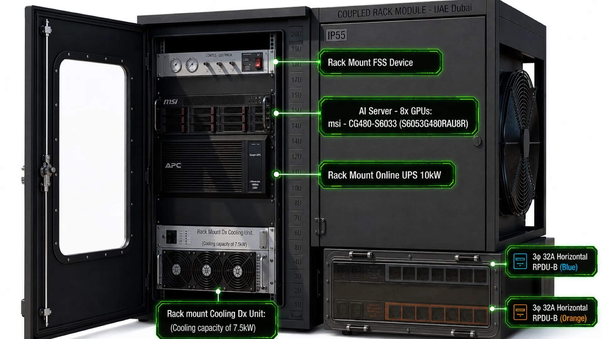
Coupled rack module · UAE Dubai · render for illustration only
~5.8 kW
Typical AC draw
~7.3 kW
Peak AC draw
~5.2 kW
GPUs capped to 400 W
Platform specification
- GPU
8 × NVIDIA RTX PRO 6000 Blackwell Server Edition
600 W per GPU · ~4.8 kW total
- CPU
2 × AMD EPYC 9575F
64 cores @ 3.3 GHz per socket
- Memory
1.5 TB DDR5-6400
24 × 64 GB · one DIMM per channel
- Storage
8 × 7.68 TB U.2 NVMe SED
+ 2 × 960 GB RAID-1 boot
- Network board
NVIDIA BlueField-3 DPU B3220
on-board
- On-board network
2 × 10GbE RJ45 LAN
- I/O budget
128 PCIe lanes per socket
feeds 8 GPUs, DPU and NVMe
- Security
On-board TPM · self-encrypting drives
- Form factor
4U rack-mount
front-to-rear airflow
Note · 600 W per GPU — roughly 4.8 kW of GPU power in a single 4U chassis, cooled by a sealed closed-loop DX system with no air exchanged with ambient.
Configuration range
Four to sixteen GPUs, in one architecture.
GPU count is not an isolated choice — cooling capacity, UPS rating and rack height scale with it.
20U + 3U coupled
Rack height
At sixteen accelerators the condenser and the incoming three-phase feed become the binding constraints rather than the compute. 8× is the proof-of-concept baseline; the 4× and 16× figures are indicative, pending design freeze.
Accelerator options
Not tied to one GPU.
The enclosure, cooling circuit and power chain are specified against watts and form factor — not a part number.
| Accelerator class | Board power | Effect on the node | Status |
|---|---|---|---|
| RTX PRO 6000 Blackwell SE | ~600 W | Baseline — eight fit within the 7.5 kW sealed air-cooled envelope. | Baseline |
| H200 — PCIe / NVL class | ~600 W | Comparable envelope to baseline; count and plant ratings broadly unchanged. | Within envelope |
| H200 — SXM class | ~700 W | Reduced count at baseline cooling, or an uprated cooling and UPS package. | Plant up / count down |
| B200 class | ~1,000 W | Eight parts alone exceed the baseline cooling duty. Count down, or plant up. | Plant up / count down |
| B300 / Blackwell Ultra class | ~1,200–1,400 W | Beyond sealed air cooling at 50 °C in this footprint — direct liquid becomes the path. | Liquid required |
The binding constraint is heat rejection, not compatibility. Above roughly one kilowatt per part the cooling envelope — not the chassis or the slot count — decides how many the node carries. Board power is indicative, confirmed against current datasheets at design freeze.
Appendix A
Specification summary.
The complete envelope in one table — enclosure, environment, thermal, power, protection and monitoring.
Enclosure
01- Rating
- IP55, sealed — zero air exchange with ambient
- Primary rack
- 20U outdoor cabinet + coupled 3U distribution rack
- Shell
- PIR sandwich panel over mineral insulation, UV-stable C4+ coating
- Mounting
- Prepared slab or 600 mm plinth, top-mounted condenser
Environment
02- Design ambient
- 50 °C continuous, excursions to 55 °C, direct sun
- Internal band
- 18–25 °C at equipment intake under varying utilisation
- Ingress
- Dust, sand, salt aerosol and humidity excluded by construction
Thermal
03- Type
- Precision DX, closed loop, inverter-driven compressor + EC fans
- Capacity
- 7.5 kW net sensible at 50 °C ambient (baseline 8× config)
- Condenser
- High-ambient, rated +55 °C, vertical upward discharge
- Fail-safe
- Alarm → staged GPU capping → graceful shutdown → door release
Power
04- Sources
- Solar PV (priority) + grid, via automatic transfer switch
- Inverter
- 15 kW
- UPS
- 10 kW rack-mount online, double conversion, ~3:45 min at load
- Distribution
- 400 V 3φ+N 50 Hz, TN-S, 63 A main, five outgoing ways
- Aggregate design load
- ~11 kW (node ~7.3 kW peak + cooling ~2.5–3.5 kW)
Protection
05- Detection
- Optical smoke + heat on the internal return-air path
- Suppression
- Self-contained rack-mount clean-agent unit
- Interlocks
- Fan/compressor stop, damper close, node power off, door secure
Monitoring
06- Local
- 7-inch door-mounted HMI acting as local DCIM head-end
- Northbound
- Modbus TCP, SNMP v3, MQTT to central DCIM or NOC
- Functions
- Trending, event logging, remote alerting, setpoint control
Appendix C · Component specification policy
Thermal, power and protection components are specified by function and measured performance rather than by manufacturer. Compute silicon and the server platform are named, because platform behaviour under sustained thermal load is the central subject of the proof of concept.